Concurrent Modeling
-
Signal assignment statements
-
Drivers and waveforms
-
Conditional Signal assignment
-
Selected signal assignment
-
Concurrent procedure calls
-
Assertion Statements
-
Guarded blocks, signal assignment
-
Bus resolution functions
-
Generate Statements
Key to Dataflow Modelling:
Concurrent Signal Assignment
sig_identifier <= waveform ;
When the value of any signal appearing in the waveform expression
on the right hand side changes, the expression is evaluated and the value
of sig_identifier is updated.
High Level Design - Dataflow View
        -- multiphase clock
type phases is ( ph1, ph2, ph3, unknown)

-- instruction format for processor
type xregs is (ax,bx,cx,dx);
type instruction is record
        (       op : opcodes;
                src : xregs;
                dest : xregs;  )
-- diagonal microinstruction format
type microps is record
        ( . . .
                func : ALU_ops
                . . .
        )
type word is std_logic_vector ( 0 to REGSIZE-1);

signal IR : instruction;
signal clock : phases := p1;
signal A_bus, B_bus, O_bus : word bus;
signal Register_file : array (xregs) of word register;

with clock select
clock <= ph1 after t3 when ph3,
        ph2 after t1 when ph1,
        ph3 after t2 when ph2;

p1:     block  (clock = ph1) begin
A_bus <= guarded Register_file ( IR.dest );
B_bus <= guarded Register_file ( IR.src );
end block  p1;

p2:     block  (clock = ph2) begin
O_bus <= guarded ALU ( A_bus, B_bus, ctl.func);
end block  p2;

p3:     block  (clock = ph3) begin
Register_file (IR.dest) <= guarded O_bus;
end block  p3;
Low Level Design - Dataflow View
Example: Here is an ALU_slice presented in dataflow format.
architecture Dataflow of ALU_slice is
begin

Cy_out <=  ((not Cy_in) and (not M) and ((X and Y and func_sel(3)) nor
                (X and not Y and func_sel(2)))) nor
                        ((not M) and (not (((not Y) and func_sel(1)) or
                                (Y and func_sel(0)) or X ))))   after 20 ns;

F <=  ((( Y and func_sel(3) and X) nor
        (X and func_sel(2) and (not Y))) xor
                (not (((not Y) and func_sel(1)) or
                        (func_sel(0) and Y) or X ))) xor
                                ( (not c1) nand (not M) )  after 20 ns;

end ALU_slice;
Structural aspects of the design: No explicit connecting signals are
used, but the view is still close enough to structure that they could be
easily inferred.
Behavioral aspects of the design: The use of the logical operators
makes this a formal declaration of behavior at a low level.
After 20 ns provides timing behavior not provided at the same level
in purely structural models.
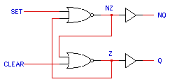
Another Low Level Dataflow Example

entity rs_latch is
port (set, clear : in
std_logic; q,nq : out std_logic)
begin
assert set = '0'
or clear = '0' -- (else)
report "RS latch inputs both high"
severity Warning;
end;
architecture dataflow of rs_latch is
signal z, nz : std_logic
:= 'X';
begin
nq <= nz;
nz <= z nor set after
10 ns;
q <= z;
z <=
nz nor clear after 10 ns;
end;
After 10 ns means that the value of z is be updated 10 ns
after the change which occurred in nz or clear.
The weird order of the statements above is intended to show that the
signal assignments do not occur in any order -- just like structural instantiation
of components. Execution of a statement is triggered when a signal or variable
on the right hand side changes value.
Also note that it is essential to have the internal z and
nz signals to be read inside the architecture since q
and nq are out signals and cannot be read.
If we were to change the port declarations to make them inout it
would allow externally driving the q and nq signals back into this module.
The function of the circuit would be different!
Also note that there is no notion of clocking implied here either.
Models of Time Delay

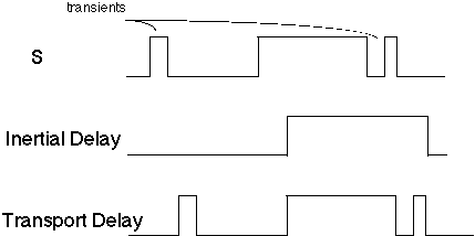
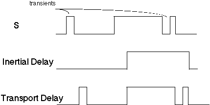
Inertial
Transient inputs are ignored.
This model is only a rough approximation of physical inertial delay
since a signal assignment is susceptible to removal all the way up to the
after delay time. But "after delay" is much like propagation
delay, while inertial delay periods typically represent input behavior
-- independent and frequently shorter.
Inertial delay is the default model used in VHDL for signal assignment.
Y <= X after T ;
Example:        a <= '0', '1' after 4 ns;
                b <= '1', '0' after 5 ns;
                y <= a xor b after 10 ns;
When a becomes '1' after 4 ns, a xor b is evaluated, and y is scheduled
to go to '0' at 14 ns. However, when b <= '0' at 5 ns, a xor b is evaluated
again, and the y <= '0' @ 14ns is removed before the y <= '1' is
scheduled @ 15ns.

Transport
Example:        a <= '0', '1' after 4 ns;
                b <= '1', '0' after 5 ns;
                y <= transport a xor b after 10 ns;
When a becomes '1' after 4 ns, a xor b is evaluated, and y is scheduled
to go to '0' at 14 ns. However, when b <= '0' at 5 ns, a xor b is evaluated
again and the y <= '1' is scheduled @ 15ns.
The 1 ns of y being '0' is not removed.
Waveforms
Concurrent signal assignments may prescribe not only one signal
updating event, but many. The general form is
sig_identifier <= val_expr after delay
{ , val_expr after delay } ;
where the curly brackets mean the enclosed part may be repeated any number
of times. The delays must have values occurring in ascending order.
The list of updating transactions (i.e. values and times) is called a
Driver of sig_identifier.
Example:
OS_out <= OS_in, '0' after Tperiod ;
Example: The following is useful to test the RS_latch:
-- S
C
Set_Pattern <= '1',
-- 1
0
'0' after 20 ns,
-- 0
0
-- no change at 40 ns 0
1
-- no change at 60 ns 0
0
'1' after 80 ns;
-- 1
1
Clear_Pattern <= '0', --
1 0
-- no change at 20 ns
0 0
'1' after 40 ns,
-- 0
1
'0' after 60 ns,
-- 0
0
'1' after 80 ns;
-- 1
1
(These two concurrent VHDL statements will be executed only once, at
initialization time.)
Copyright 1998, Ben M. Huey
Copying this document without the permission of the author is prohibited
and a violation of international copyright laws.
Rev. 2/20/98 B. Huey